Stylized Attack Cone Indicator Shader
In this tutorial we will implement a simple, stylized attack cone shader in Unity. The core ideas behind every step will be explained so that following in a different engine shouldn’t be too difficult.
By the time we are done we will have an effect that looks similar to the following:
(The assets in the above video were created by the talented Kay Lousberg)
Setup
We will start by creating a new unlit shader with the following basic setup:
1
2
3
4
5
6
7
8
9
10
11
12
13
14
15
16
17
18
19
20
21
22
23
24
25
26
27
28
29
30
31
32
33
34
35
36
37
38
39
40
41
42
43
44
45
46
47
48
49
50
51
52
53
54
55
56
57
58
59
60
61
62
63
64
65
66
Shader "Custom/AttackCone"
{
    Properties
    {
        [HDR] _Color ("Color", Color) = (1.0, 1.0, 1.0, 1.0)
    }
    SubShader
    {
        Tags
        {
            "RenderType" = "Transparent"
            "Queue" = "Transparent"
            "IgnoreProjector" = "True"
        }

        ZWrite Off
        Blend SrcAlpha OneMinusSrcAlpha
        BlendOp Add

        LOD 100

        Pass
        {
            CGPROGRAM
            #pragma vertex vert
            #pragma fragment frag

            #include "UnityCG.cginc"

            struct appdata
            {
                float4 vertex : POSITION;
            };

            struct v2f
            {
                float4 vertex : SV_POSITION;
                float4 localPos : TEXCOORD0;
                float4 worldPos : TEXCOORD1;
            };

            // Passed from player script
            float4 playerForward;
            float4 playerPosition;

            fixed4 _Color;

            v2f vert (appdata v)
            {
                v2f o;

                o.localPos = v.vertex;
                o.worldPos = mul(unity_ObjectToWorld, v.vertex);
                o.vertex = UnityObjectToClipPos(v.vertex);

                return o;
            }

            fixed4 frag (v2f i) : SV_Target
            {
                return _Color;
            }
            ENDCG
        }
    }
}
Moving on create a material that makes use of the above shader (look for “Custom -> AttackCone”).
We will use a plane as the base mesh to apply this material and create our effect, so add a plane to your scene and set the material in its Mesh Renderer to the one created above.
For future reference, this is what our scene looks like after the setup:
 Setup result
Shader Base Explanation
Let’s have a look at some interesting things that are already happening in the shader:
1
2
3
4
5
6
7
8
9
10
Tags
{
    "RenderType" = "Transparent"
    "Queue" = "Transparent"
    "IgnoreProjector" = "True"
}

ZWrite Off
Blend SrcAlpha OneMinusSrcAlpha
BlendOp Add
We want to be able to modify the alpha channel of our cone so we need to leverage transparency. Here, we set the appropriate RenderType and rendering Queue and we ignore projectors (you may not want to do that if you use a decal pipeline for the effect).
We also disable writing to the ZBuffer and set the blending state. If you are not familiar with how blending works, imagine the following:
- The fragment shader generates a color for every drawn pixel of our object.
- The renderer wants to write that pixel on the framebuffer by blending it with whats already drawn there.
- In order to do this successfully, the renderer uses the currently set blending state to combine the colors. In our case it will be:
SrcAlpha * SrcColor + (1 - SrcAlpha) * DstColor - Source (Src) is the output of the fragment shader and destination (Dst) is the pre-existing value in the framebuffer we want to draw on.
1
2
3
4
5
6
7
8
9
10
11
struct appdata
{
    float4 vertex : POSITION;
};

struct v2f
{
    float4 vertex : SV_POSITION;
    float4 localPos : TEXCOORD0;
    float4 worldPos : TEXCOORD1;
};
These are the structs that we use as input argument types in the vertex and fragment stages. For the vertex stage we only need the vertex data (object space position) and for the fragment stage we need the local and world position mapping of each pixel. We will not be using the float4 vertex : SV_POSITION; field ourselves but it is required for the rendering pipeline to work properly.
1
2
3
// Passed from player script
float4 playerForward;
float4 playerPosition;
These are variables that we set from our player/object C# script by calling the respective material SetVector(...) function. We don’t need them as a starting point but it’s always nice to make our shaders position/rotation independent from the get go.
1
2
3
4
5
6
7
8
9
10
v2f vert (appdata v)
{
    v2f o;

    o.localPos = v.vertex;
    o.worldPos = mul(unity_ObjectToWorld, v.vertex);
    o.vertex = UnityObjectToClipPos(v.vertex);

    return o;
}
Pretty standard vertex function. We just calculate the local, world and screen space position values of our vertex.
Circular Clipping
Our cone is a piece of a circle, so let’s start by identifying the parts of the geometry that do not belong in one and clip them. We also want to clip the pixels that belong to a small circle around the center of the object to create a nicer effect.
Write the following code in the fragment shader:
1
2
3
4
5
6
7
8
9
const float3 playerToPoint     = (i.worldPos.xyz - playerPosition.xyz) * float3(1.0, 0.0, 1.0);
const float3 playerToPointNorm = normalize(playerToPoint);

const float coneRadius         = 5.0f;
const float minRadius          = 0.7f;
const float distance           = length(playerToPoint);

clip(coneRadius - distance);
clip(distance - minRadius);
We start by calculating the player-to-current-point vector and its normalized form. We will make extensive use of these 2 vectors throughout the fragment stage.
Then we define the radius of the grater and smaller circles.
Finally we clip pixels that belong outside the grater circle or inside the smaller one.
The result should look something like this:  Circular clipping
If you don’t see any clipping, make sure the extends of your plane are greater than the specified cone radius.
Cone Clipping
Moving on, we clip the pixels of the circle that are outside of a specified cone angle:
1
2
3
4
const float coneAngle = 45.0;
const float pointToForwardAngle = acos(dot(playerToPointNorm, playerForward.xyz)) * 180.0 * UNITY_INV_PI;

clip(coneAngle - pointToForwardAngle);
Here we defined cone angle and find the angle between the object/player forward vector and the player-to-point vector (normalized) by using the dot product. Make sure both of the vector arguments to the dot product are normalized or you may see some “angular” artifacts happening. After we find the angle, we clip pixels that our outside our specified range.
At this point, the object should look similar to the following: 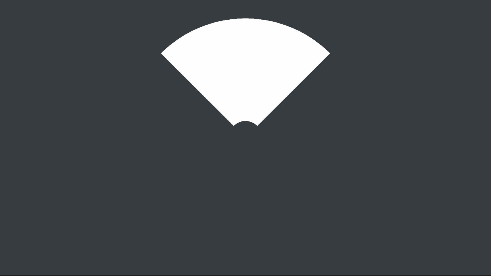 Cone clipping
Note that the total angle of the cone is
2.0 * coneAnglesince we use that variable to check both sides of the forward vector.
Outline Detection
At this point we have successfully adjusted our mesh to the desired cone shape and we can focus on improving its visual style. Let’s start by adding an outline to make it stand out.
There are two steps to achieve that. The first is to detect the outline on the circular parts of the cone. The second is to detect the outline on the sides. Let’s start with the first one which is easier:
1
2
3
4
5
6
7
8
9
10
11
12
13
14
15
16
const float sdfCircleMin = abs(distance - minRadius);
const float sdfCircleMax = abs(distance - coneRadius);

const bool outline = sdfCircleMin < outlineSize || sdfCircleMax < outlineSize;

fixed4 outColor = _Color;
if (outline)
{
    outColor.a = 0.9;
}
else
{
    outColor.a = 0.2;
}

return outColor;
We use the circle SDF function to compare the radius of our circles with distance of each respective pixel from the center. Then we combine the results in the outline bool. Depending on if the object is part of the outline or not we modify its alpha value. At this point we also use an intermediate variable outColor to make our lives easier (remember to replace the return variable as above).
The result should look like this: 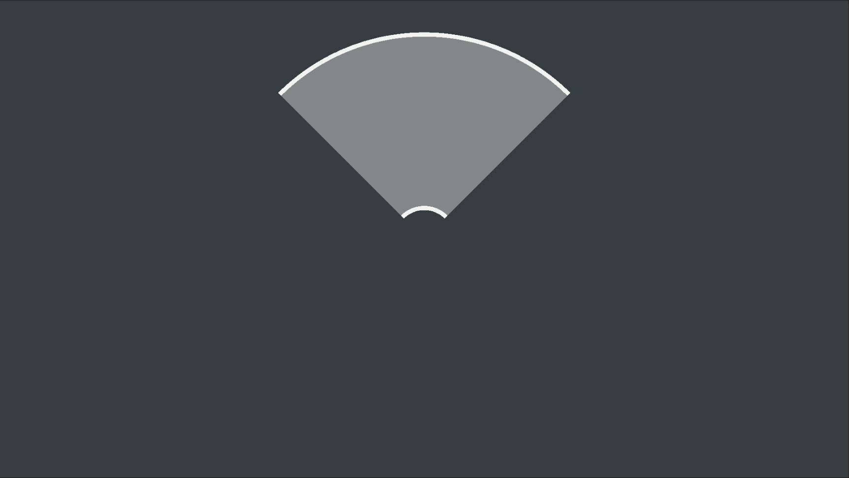 Circles outline
Let us pause for a moment to discuss how we can detect the sides outline. At a first glance it might look like we can apply the same technique we did with the cone clipping, compare the angle between the player-to-point and object forward vectors to the cone angle. However, if you do that you will notice that the outline thickness is not consistent across its radius: 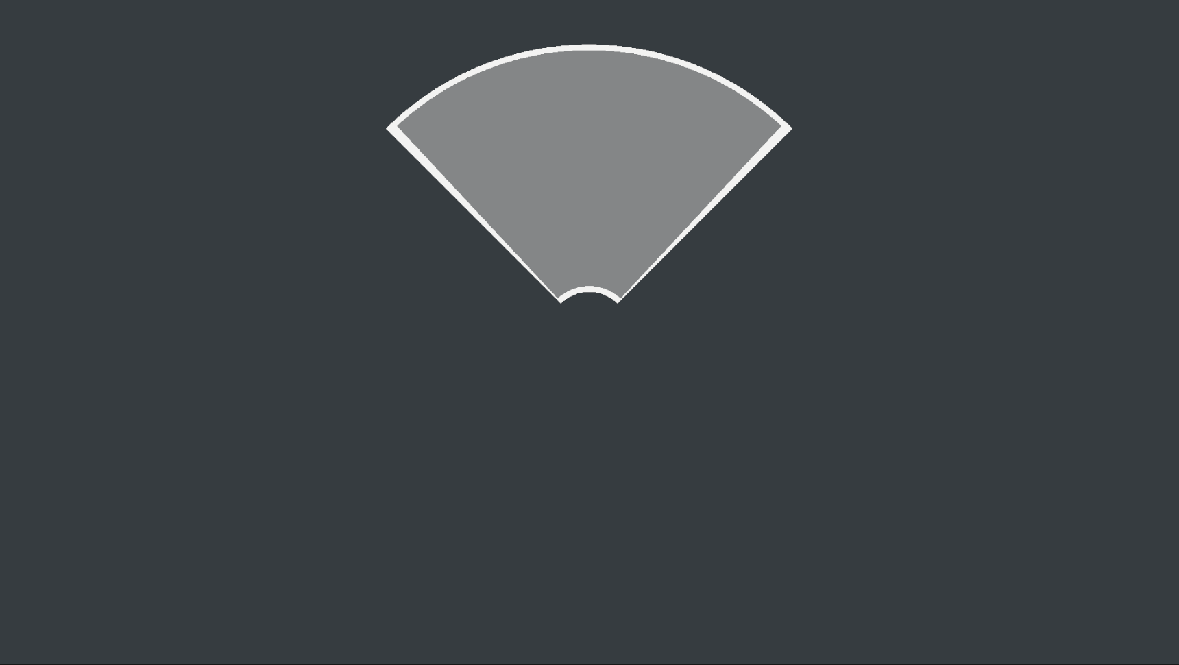 Radial calculation of the sides outline (incorrect)
The solution to this issue is probably the most complicated part of this shader. What we need is to calculate the world space distance from the current pixel to the lines that align with the sides of the cone. Breaking it down into simpler steps we need to:
- Find the vectors that start from the center of the object and align with the sides
- Project the world position of the current pixel to each of the side vectors
- Calculate the length of the vector
Here’s the code that implements these steps:
1
2
3
4
5
6
7
8
9
10
11
12
13
14
15
16
17
18
19
20
21
22
23
24
25
26
27
28
29
30
const float sinTheta = sin(radians(coneAngle));
const float cosTheta = cos(radians(coneAngle));

const float4x4 rotMatrixRight = float4x4(
    cosTheta, 0.0, sinTheta, 0.0,
    0.0, 1.0, 0.0, 0.0,
    -sinTheta, 0.0, cosTheta, 0.0,
    0.0, 0.0, 0.0, 1.0
    );

const float4x4 rotMatrixLeft = float4x4(
    cosTheta, 0.0, -sinTheta, 0.0,
    0.0, 1.0, 0.0, 0.0,
    sinTheta, 0.0, cosTheta, 0.0,
    0.0, 0.0, 0.0, 1.0
    );

const float3 lineRight     = mul(rotMatrixRight, playerForward * _AttackRadius);
const float3 lineRightNorm = normalize(lineRight);
const float3 projRight     = lineRightNorm * (dot(playerToPointNorm, lineRightNorm) * distance);

const float3 lineLeft      = mul(rotMatrixLeft, playerForward * _AttackRadius);
const float3 lineLeftNorm  = normalize(lineLeft);
const float3 projLeft      = lineLeftNorm * (dot(playerToPointNorm, lineLeftNorm) * distance);

const float distLineLeft   = length(playerToPoint - projLeft);
const float distLineRight  = length(playerToPoint - projRight);

const bool outline = sdfCircleMin < outlineSize || sdfCircleMax < outlineSize
        || distLineRight < outlineSize || distLineLeft < outlineSize;
First we create the rotation matrices rotMatrixRight and rotMatrixLeft that rotate a vector around the Y (up) axis by coneAngle degrees. Applying this rotation to the playerForward vector gives us the vectors we were looking for. We also calculate their normalized form. Then we calculate the respective projections and the length of the vectors from the end of the projection to the point, in the distLineLeft and distLineRight variables. If that length is smaller than the preferred outline size then this pixel is part of the outline. Lastly we expand the outline variable calculation to include this check.
The results look like this: 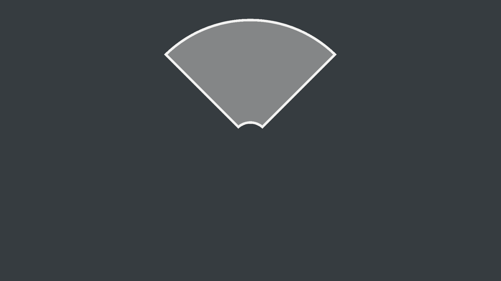 Correct sides outline calculation
There is one last case that we need to take care of. Setting the coneAngle variable to a value greater than 90 gives the following weird results: 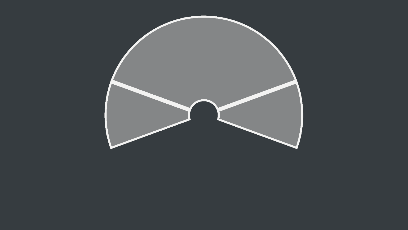 Weird outline for a cone angle > 90
This happens because the projection vector can end up in both “possitive” and “negative” directions (compared to the side vectors). The solution to this is not very hard. We need one more check to reject points that form an angle greater than 90 degrees with the side in question:
1
2
3
4
5
const bool isSameHalfSpaceRight = acos(dot(playerToPointNorm, lineRightNorm)) < UNITY_HALF_PI;
const bool isSameHalfSpaceLeft  = acos(dot(playerToPointNorm, lineLeftNorm)) < UNITY_HALF_PI;

const bool outline = sdfCircleMin < outlineSize || sdfCircleMax < outlineSize
        || (distLineRight < outlineSize && isSameHalfSpaceRight) || (distLineLeft < outlineSize && isSameHalfSpaceLeft);
As expected, we update the outline variable to include this check.
We now get a correct outline for all sorts of angles:
Theres one last edge case we didn’t care of. When the
coneAngleis 180 degrees we form a complete circle and the sides outline makes no sense anymore. Solving this is fairly easy, we just remove the cone side checks and calculations. The solution is omitted from the given code.
Color Gradients and Fill Amount
Now that we are done with the shape and outlines let’s make everything look a little more interesting.
Apart from area of effect, attack indicators are commonly used to provide a sense of progression during the time of casting a spell or attack. Let’s add some color gradients and a fill amount to make the effect look more appealing in that sense:
1
2
3
4
5
6
7
8
9
10
11
12
13
14
15
16
17
18
19
20
21
22
23
24
25
const fixed4 colorStart       = fixed4(0.08, 0.90, 0.23, 1.0);
const fixed4 colorEnd         = fixed4(0.05, 0.42, 0.20, 1.0);
const fixed4 colorChargeStart = fixed4(0.90, 0.20, 0.17, 1.0);
const fixed4 colorChargeEnd   = fixed4(0.39, 0.04, 0.09, 1.0);

const float fillAmount        = 0.75f;
const float charge            = fillAmount * coneRadius;

const float sdfCharge         = abs(distance - charge);

const bool outline = sdfCircleMin < outlineSize || sdfCircleMax < outlineSize
        || (distLineRight < outlineSize && isSameHalfSpaceRight) || (distLineLeft < outlineSize && isSameHalfSpaceLeft)
        || sdfCharge < outlineSize * 0.5;

const float interp = clamp(distance / coneRadius, 0.0, 1.0);
fixed4 outColor = fixed4((interp * colorEnd + (1.0 - interp) * colorStart).xyz, 0.2);

if (outline)
{
    outColor.a = 0.9;
}
else if (distance < charge)
{
    outColor = interp * colorChargeEnd + (1.0 - interp) * colorChargeStart;
}
Here we have added 4 color variables: colorStart and colorEnd are used to interpolate the base/main color of the indicator while colorChargeStart and colorChargeEnd are used to interpolate the color of the “filled” indicator.
The fillAmount and charge variables were added to manage the fill levels of the effect.
We also expanded the outline to include an extra layer at the extend of the current fill level, so it’s more visually clean, using the sdfCharge < outlineSize * 0.5 (we use the same method we did for circles to calculate sdfCharge).
The variable interp holds the interpolation delta based on the world distance of the pixel to the center of the object, divided by the total radius of the effect.
Finally, we apply a simple linear interpolation (lerp) to the outColor based on whether the pixel is part of the outline or part of the “filled” cone (notice the change to the initial variable assignment and the addition of condition in the else if case).
Here is the final result:
Conclusion
At this point, there are multiple things you may want to try out to take the effect to the next level. There are also many optimizations we could do to improve the above shader and make it cleaner. The obvious one is the exposure of the local variables to the greater context so you can interact with them from a script.